Battery Tester Project
Battery
Tester Project Using LM3914 IC
This objective of this project is to design and build a
battery tester that is able to test various types of dry cell and rechargeable
battery with a voltage of less than 2V. Configured as a bar graph battery level
indicator, the LM3914 IC from National Semiconductor senses the voltage levels
of the battery under test and drives the 10 LEDs to ON or OFF based on the
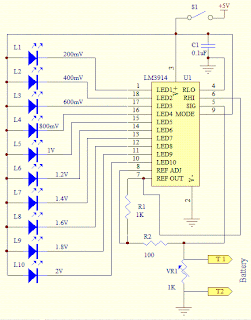
voltage that is detected. The current driving the LEDs is regulated by using
the external resistor R1 and hence limiting resistors are not required.
The schematic shows the simple connections where the
reference voltage at pin 8 of U1 can be adjusted by adjusting the variable
resistor VR1. The voltage at pin 8 will set the maximum scale of the LED. In
testing dry cell battery of 1.5V,set the voltage at pin 8 to 2.0V. Each of the
LED will thus represent 200mV when lighted up.
Test the circuit by using a breadboard before soldering the
parts onto the PCB. This is to ensure that all the components that are used are
in working condition. This is one of the simplest and interesting project that
you can embark on if you have not try any project using this integrated circuit
and the use of light emitting diodes.
If testing of rechargeable battery such as NiCd or NiMH is
required, set the reference voltage to a lower value such as 1.5V as the
typical voltage of a rechargeable battery is approximately 1.2V.
When testing the battery, take note of the polarity of the
probe to the terminals of the battery. T1 is to be placed on the positive
terminal and T2 the negative terminal of the battery.
A digital or analog multimeter that is set to measure the
voltage of the battery is necessary. The voltage that is measured is used as a
standard against the voltage that is displayed on the LEDs.


No comments:
Post a Comment